Work
Selected professional experience and projects. The first three have full write-ups, followed by smaller projects. My accelerator-memory research is on the research page.
Embedded · Python · Summer 2025
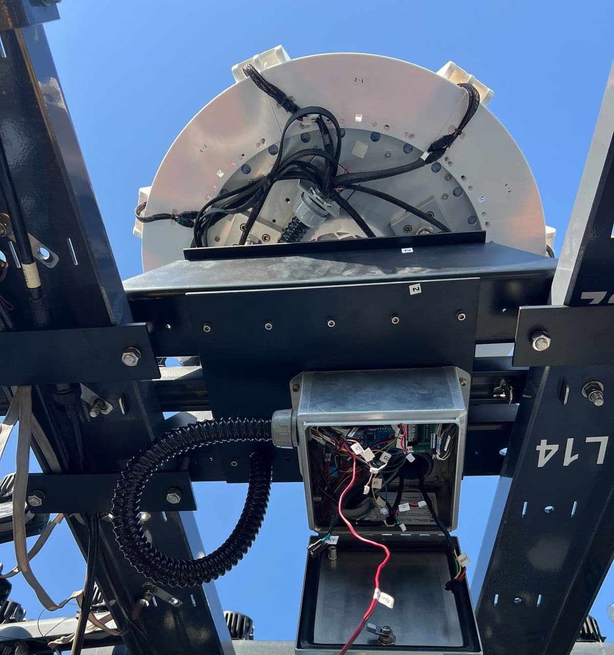
Shade control and star calibration for an observatory camera array
A fail-safe for the sun-shade controller in the Galileo Project's camera enclosures, and a star-field pipeline that solves each visible camera's orientation.
FPGA · SystemVerilog · 2026
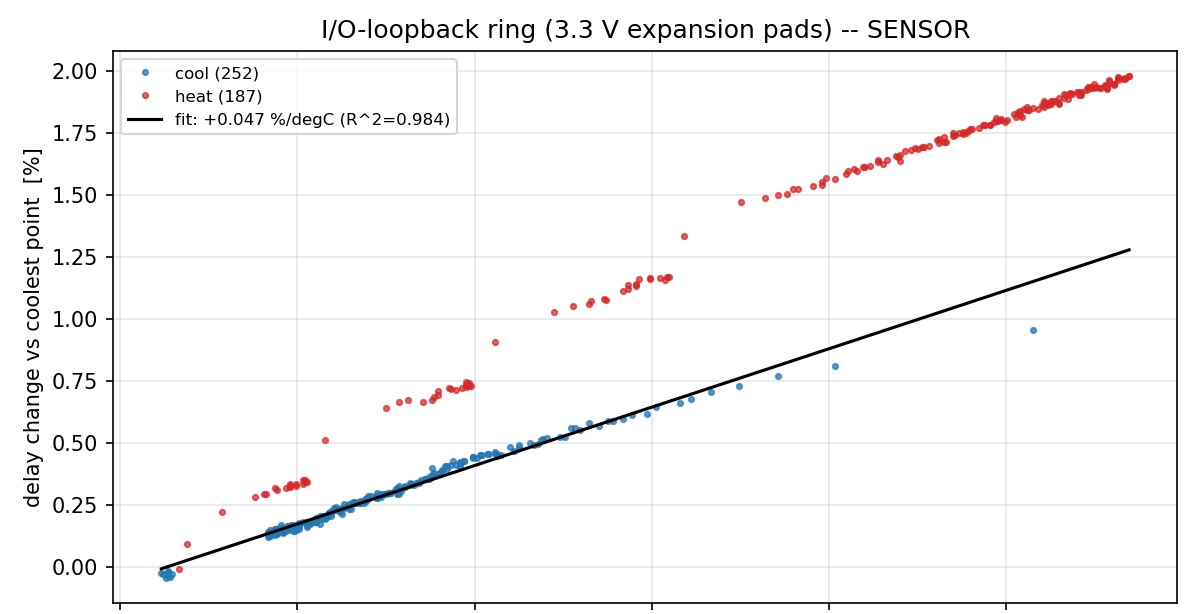
Propagation delay vs. die temperature on an FPGA
Ring oscillators through the 3.3 V I/O buffers and the 1.0 V core, hardware frequency counters, fabric heaters with a supply governor, and XADC telemetry on an Artix-7. Built for the CS 1410 labs.
EDA · TypeScript · 2026
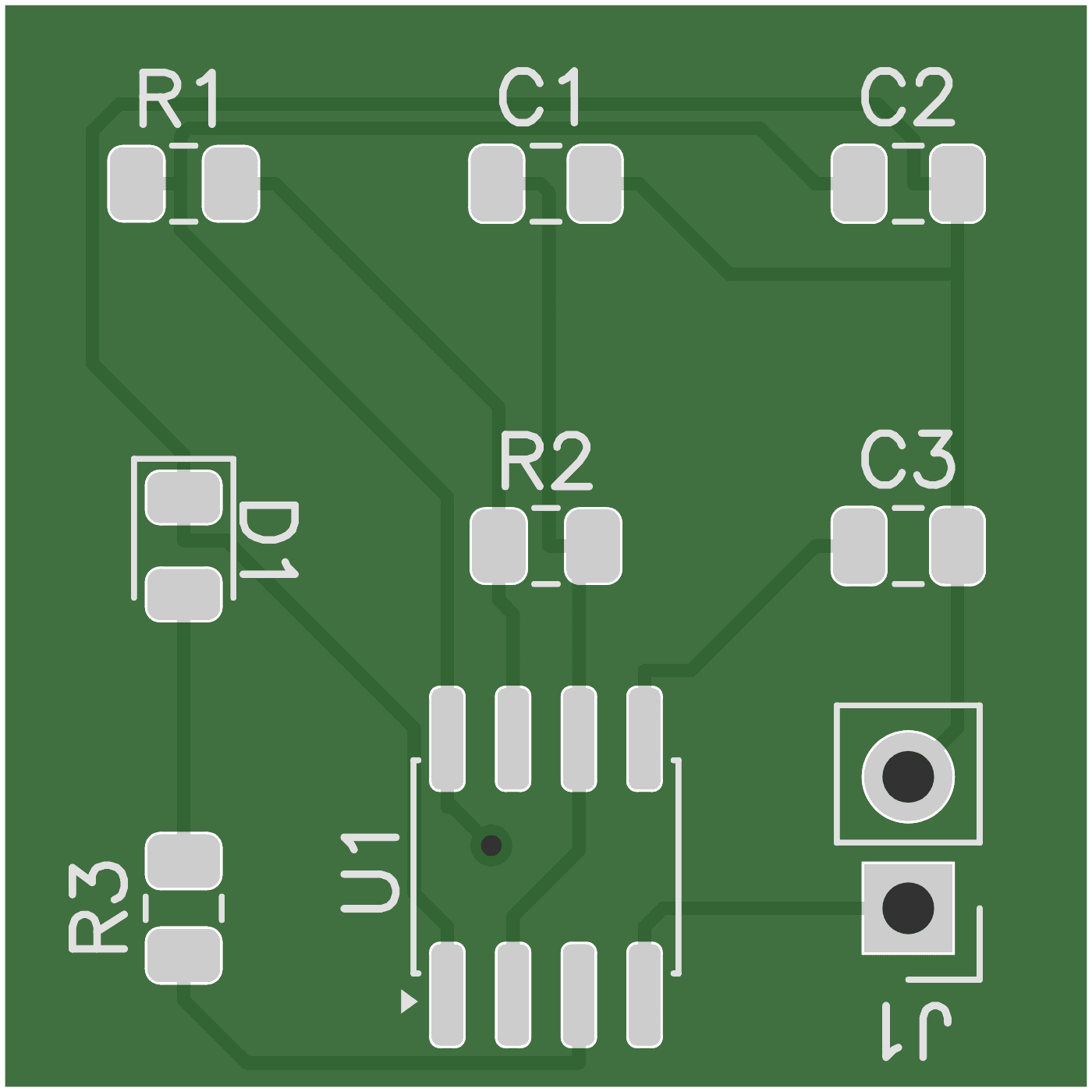
Sirkit: from a circuit description to checked fabrication files
An EDA pipeline that builds a netlist from KiCad-library parts, places and routes a two-layer board, and writes Gerber and drill files only after DRC, parity and parse-back checks pass. JLCPCB fabricated a generated board, and it works.
Smaller projects
Verilog · January 2026
Gate-level 32-bit ALU
A 32-bit ALU built only from gate primitives: AND, OR, add, subtract, set-less-than, and logical and arithmetic shifts, with zero, negative and overflow flags. The adder is two 16-bit carry-lookahead blocks (each made of 4-bit lookahead groups) with the carry passed between the halves, and the shifter is a five-stage mux network that reverses the bits for left shifts. A self-checking testbench compares every result and flag against a behavioral model over 24 directed and 50 random cases.
SystemVerilog · CS 1410 lab · fall 2025
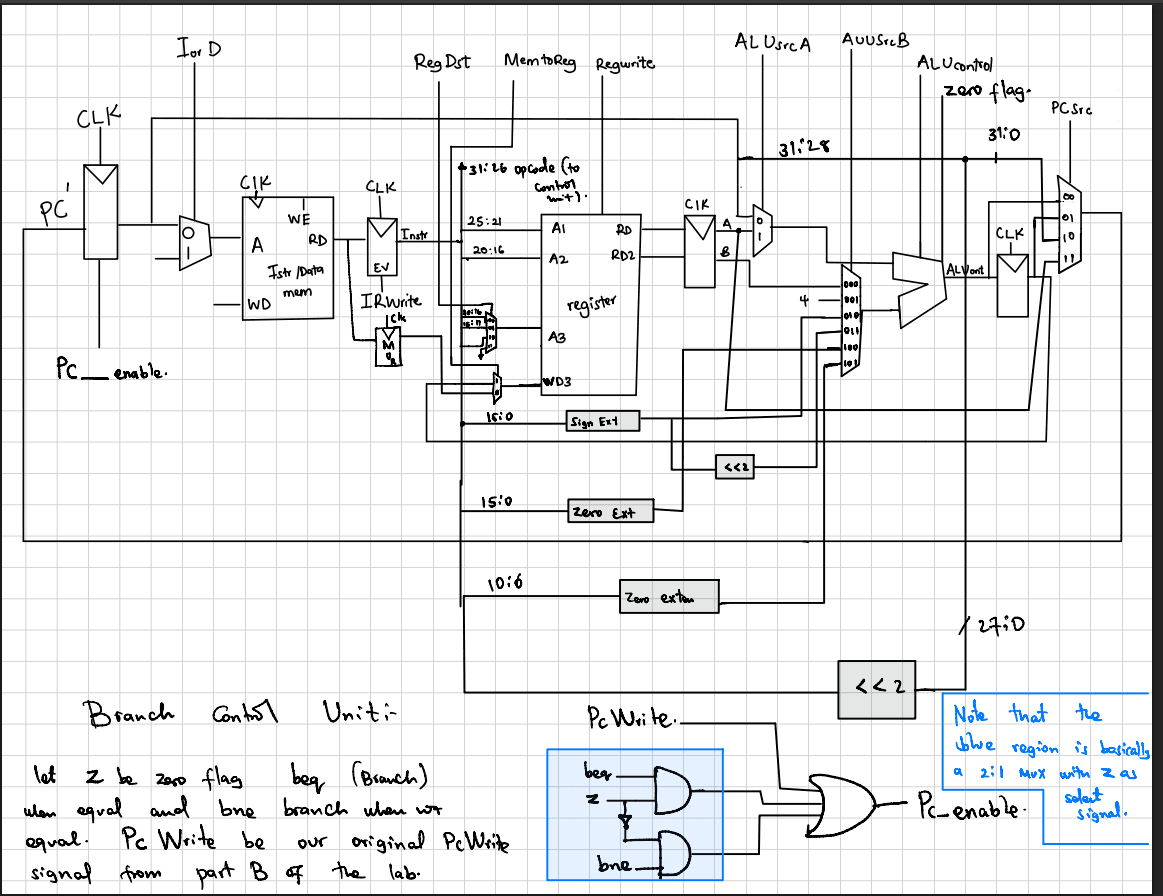
Multicycle MIPS CPU
A 32-bit multicycle MIPS processor for CS 1410’s processor lab: a 15-state control FSM, a register file, and a datapath with PC, IR, MDR, A, B and ALUOut registers. It decodes 22 instructions (R-type arithmetic, logic and shifts, immediates, loads and stores, beq/bne, j, jal and jr) and runs on the XEM7310, with its memory loaded and read back over FrontPanel. The core runs from a divided clock of about 10 MHz.
LTspice · ES 152 project
Two-channel AM link
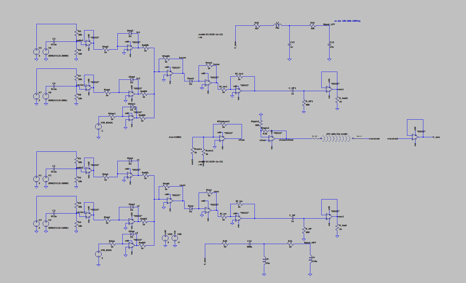
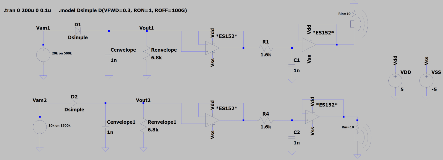
A frequency-multiplexed AM system simulated in LTspice. Each transmitter channel multiplies an audio tone onto its carrier with an analog multiplier built from op-amps and diodes: log amplifiers on both inputs, a summing stage, and an exponential amplifier, so that adding logarithms multiplies the signals. Channel 1 puts 20 kHz on a 500 kHz carrier and channel 2 puts 10 kHz on 1.5 MHz. The two are summed, amplified and passed through a link model, then separated with an LC low-pass and an LC high-pass filter. Each receiver recovers its tone with a diode envelope detector (1 nF and 6.8 kΩ) followed by an RC low-pass and a buffer driving a speaker load.
Proteus · Harvard Undergraduate Robotics Club
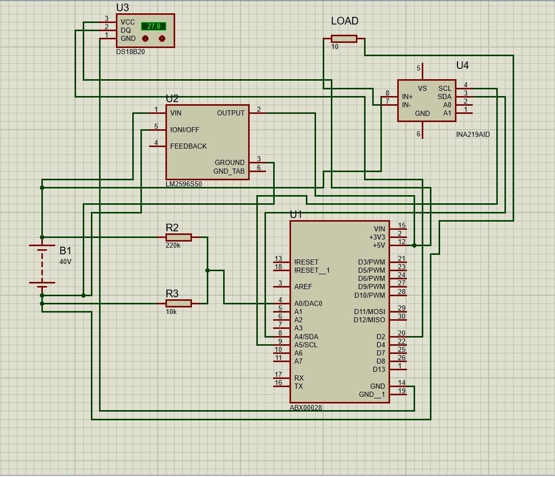
Battery monitor for the rover
A battery-monitor design for the robotics club’s University Rover Challenge rover. An Arduino Nano Every reads pack current and bus voltage from an INA219 over I²C for coulomb counting, temperature from a DS18B20 on a one-wire bus, and the pack voltage through a 220 kΩ / 10 kΩ divider (a 40 V pack reads about 1.74 V at the pin). An LM2596 buck regulator makes the 5 V rail from the pack.