Embedded systems · Summer 2025
Shade control and star calibration for an observatory camera array
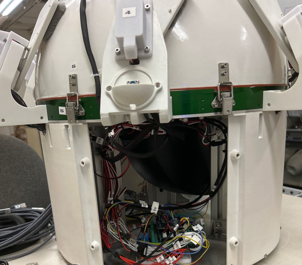
The Galileo Project at the Harvard–Smithsonian Center for Astrophysics runs sky-monitoring cameras in weatherproof enclosures (“Daleks”) at several sites, including on the Sphere in Las Vegas. Most of the enclosure hardware and firmware was designed by the project’s engineering team. Two pieces are mine and are described here: a fail-safe in the shade controller, and the star-field calibration that solves where each visible-light camera points.
- Role
- Embedded systems engineering intern, summer 2025
- Hardware
- Arduino Mega 2560 controllers, servo shades with limit switches, BME280 / TMP117 / TSL2561 sensors on I²C, PWM fans, Raspberry Pi site hosts
- Calibration
- Python, NumPy, OpenCV, Astropy, the Yale Bright Star Catalogue
- Code
- Calibration pipeline on GitHub · enclosure firmware is in the project’s private repository
The system
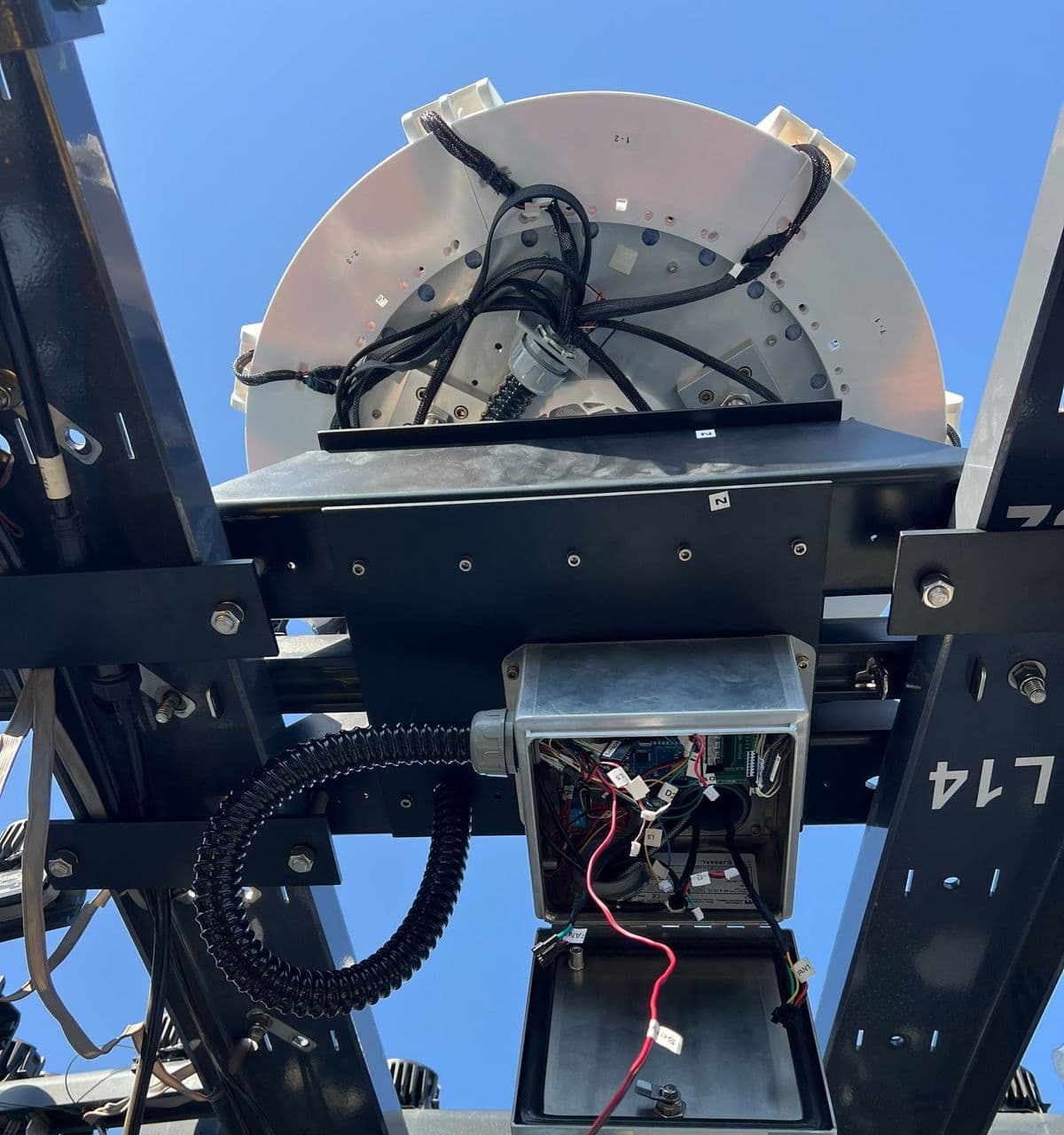
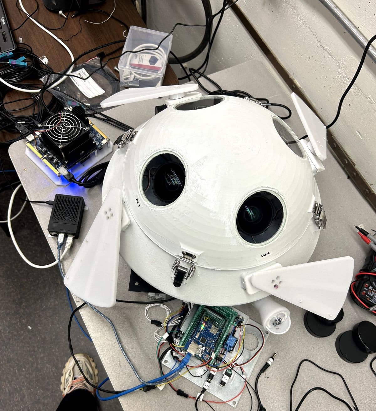
Each enclosure holds its cameras behind windows, and each window has a servo-driven shade that can close over it. The infrared enclosures have eight; the visible-light “Mini Dalek” has four cameras pointed in four directions at about 50° elevation, with a shade each. An Arduino Mega 2560 inside the enclosure runs the shades and the climate: it gets the time over NTP, computes where the sun is from the time and the site’s location, checks a light sensor, and opens or closes the shades on that schedule. The same controller reads dome and electronics temperatures, runs fans with tachometer feedback and a heater, and confirms every shade position with a limit switch. A Raspberry Pi at each site reaches the Arduinos over USB serial, both for the console and for reflashing firmware.
A safe state for a controller that has lost the time
The shade schedule is only as good as the clock. If the site loses its network connection and the Arduino’s time is no longer set by NTP, it has no idea where the sun is. In the existing logic, that case closed the shades only if the light sensor was also over its threshold, so the shades’ state depended on one sensor reading at the moment the clock was lost.
I changed the rule so that losing time sync on its own closes every shade, one at a time, and reads back each shade’s limit switch to confirm it actually closed. A camera loses some observing time while the clock is down, but it can’t be left open to the sun because of a missed sync. The change covers the three sketches that run eight-shade and four-shade enclosures.
if clock not set by NTP:           # sun position unknown
    for each shade:
        close it
        confirm with its limit switch
Solving each camera’s orientation from the stars
To turn a pixel into a direction in the sky, the project needs each camera’s orientation in world coordinates. The intrinsic calibration (focal length, principal point, lens distortion) was already known for the visible cameras; the rotation of each camera was not. Stars are an ideal target for this: their directions at a given time and place are known very precisely, and they sit at infinity, so only rotation matters.
The pipeline, per camera:
- Detect stars. Subtract a per-camera median frame to remove hot pixels and fixed glow, high-pass the image with a wide Gaussian, normalize by a robust noise estimate (1.4826 × the median absolute deviation), and keep local maxima above 6σ. Each star’s position is a flux-weighted centroid over a 7 × 7 window, and anything whose peak holds more than 60 % of the flux is rejected as a hot pixel.
- Turn pixels into rays. Undistort with the known intrinsics and convert each detection to a unit vector in the camera frame.
- Model the sky. For the frame’s capture time, compute the altitude and azimuth of every star brighter than magnitude 5.5 in the Yale Bright Star Catalogue at the site, including atmospheric refraction, and keep the bright ones in the camera’s rough field of view.
- Match by geometry. The angle between two stars doesn’t depend on how the camera is rotated, so matching needs no initial guess. For every pair of detected stars, every catalogue pair with the same separation (within 0.3°) proposes a rotation. Each proposal is scored by how many other stars it lines up within 0.4°, and the best one is refined by re-solving on its inliers.
- Solve and pool. The rotation that best aligns matched pairs is Wahba’s problem, solved with the SVD (Kabsch) method. Frames with at least five matches and a median error under 15 px are pooled for a final solve, and the reprojection error is reported as its 50th and 90th percentiles.
kab = lambda A,Bm:(lambda U,S,Vt: Vt.T@np.diag([1,1,np.sign(np.linalg.det(Vt.T@U.T))])@U.T)(*np.linalg.svd(A.T@Bm))
Results
Three of the four cameras at one of the Las Vegas sites solved:
| Camera | Azimuth | Elevation | Reprojection error (median) |
|---|---|---|---|
| North | 48.5° | 50.8° | ≈ 9 px |
| South | 225.1° | 49.1° | ≈ 6 px |
| West | 315.1° | 52.7° | ≈ 9 px |
| East | not solved: too few stars in its frames | ||
The three solutions agree with each other. Elevations are within 3° of the 50° design, and the azimuths are about 90° apart but rotated roughly 45° from the nominal compass directions, which points at how the whole enclosure was mounted rather than at any single camera. With focal lengths around 2,230–2,380 px, a 6–9 px median error is roughly 0.15–0.25° on the sky near the image center.